Questões de Concurso
Para profissional de nível superior
Foram encontradas 421 questões
Resolva questões gratuitamente!
Junte-se a mais de 4 milhões de concurseiros!
Deseja-se projetar um circuito que acenda um led, com a sua máxima intensidade luminosa, com uma tensão contínua de VF= 15 V, conforme mostra o circuito a seguir:

As especificações do led são: corrente para a máxima
intensidade luminosa: 20 mA, tensão de operação: 2,2 V.
Um resistor limitador RL que possa funcionar adequadamente, de valor e potência comercialmente disponíveis,
e que permita que se utilize uma corrente próxima da máxima sem ultrapassá-la é:
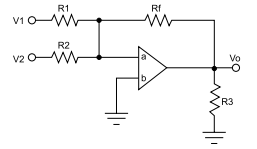
Deseja-se construir um circuito somador com um amplificador operacional ideal, no qual Rf = 2 kΩ.
Caso Vo = –2 V, V1 = 1 V e V2 = 2 V, tem-se que
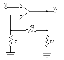
No circuito a seguir, baseado em um amplificador operacional ideal, no qual R2 = 2 kΩ, foram efetuadas as seguintes medições: Vi = 1 V e Vo = 9 V. Para que esses valores pudessem ser obtidos, o valor de
A camada inferior de cobre (bottom cooper layer) e a camada de impressão superior (top silkscreen layer) de um layout de uma placa de circuito impresso de face simples são mostradas na figura a seguir.
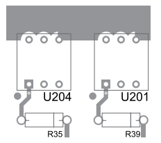
Nesse layout de placa de circuito impresso,
A partir do estabelecimento de um esquema elétrico e do diagrama de conexões, durante a elaboração do projeto de uma placa de circuito impresso, são necessárias várias etapas de design.
A respeito dessas etapas, é correto afirmar que
O circuito a seguir possui um voltímetro e um amperímetro, ambos considerados ideais. R2 = 1 Ω e R4 = 3 Ω.
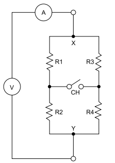
Foram efetuadas medições em duas condições:
• CH aberta: leitura do voltímetro = 6 V, leitura do amperímetro = 2 A.
• CH fechada: leitura do voltímetro = 6 V, leitura do amperímetro = 2 A.
Nessas condições, tem-se que
Deseja-se construir um circuito divisor de tensão com as seguintes características:
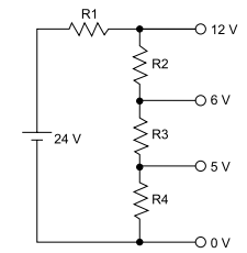
Sabendo-se que R2 = 150 Ω, tem-se que:
Em uma residência encontra-se instalado um chuveiro elétrico de potência igual a 2200 W, alimentado por uma tensão de 220 V. Considerando que esse tenha sido o único equipamento a consumir energia elétrica na residência em um período de 30 dias, a conta de energia mensal, devido ao seu uso, foi de R$ 49,50, sendo que o custo do kWh é igual a R$ 0,50.
Sobre essa situação, é correto afirmar que
1. What is an analog-digital converter?
An Analog-Digital Converter (ADC) is a widely used electronic component that converts an analog electric signal (usually a voltage) into a digital representation. The ADCs are at the front-end of any digital circuit that needs to process signals coming from the exterior world. Its schematic symbol is:

The output of a microphone, the voltage at a photodiode or the signal of an accelerometer are examples of analog values that need to be converted so that a microprocessor can work with them.
2. How does the ADC convert a signal?
Many ways have been developed to convert an analog signal, each with its strengths and weaknesses. The choice of the ADC for a given application is usually defined by the requirements you have: if you need speed, use a fast ADC; if you need precision, use an accurate ADC; if you are constrained in space, use a compact ADC.
All ADCs work under the same principle: they need to convert a signal to a certain number of bits N. The sequence of bits represents the number and each bit has the double of the weight of the next, starting from the Most Significant Bit (MSB) up to the Least Significant Bit (LSB). In a nutshell, we want to find the sequence of bits bN−1, bN−2, ..., b0 that represents the analog value Vin as Vin=∑n=0N−1bn2nVref2N.
(www.onmyphd.com/?p=analog.digital.converter. Adaptado)
No trecho da resposta à segunda pergunta – In a nutshell, we want to find the sequence of bits…–, a expressão destacada equivale, em português, a
1. What is an analog-digital converter?
An Analog-Digital Converter (ADC) is a widely used electronic component that converts an analog electric signal (usually a voltage) into a digital representation. The ADCs are at the front-end of any digital circuit that needs to process signals coming from the exterior world. Its schematic symbol is:

The output of a microphone, the voltage at a photodiode or the signal of an accelerometer are examples of analog values that need to be converted so that a microprocessor can work with them.
2. How does the ADC convert a signal?
Many ways have been developed to convert an analog signal, each with its strengths and weaknesses. The choice of the ADC for a given application is usually defined by the requirements you have: if you need speed, use a fast ADC; if you need precision, use an accurate ADC; if you are constrained in space, use a compact ADC.
All ADCs work under the same principle: they need to convert a signal to a certain number of bits N. The sequence of bits represents the number and each bit has the double of the weight of the next, starting from the Most Significant Bit (MSB) up to the Least Significant Bit (LSB). In a nutshell, we want to find the sequence of bits bN−1, bN−2, ..., b0 that represents the analog value Vin as Vin=∑n=0N−1bn2nVref2N.
(www.onmyphd.com/?p=analog.digital.converter. Adaptado)
1. What is an analog-digital converter?
An Analog-Digital Converter (ADC) is a widely used electronic component that converts an analog electric signal (usually a voltage) into a digital representation. The ADCs are at the front-end of any digital circuit that needs to process signals coming from the exterior world. Its schematic symbol is:

The output of a microphone, the voltage at a photodiode or the signal of an accelerometer are examples of analog values that need to be converted so that a microprocessor can work with them.
2. How does the ADC convert a signal?
Many ways have been developed to convert an analog signal, each with its strengths and weaknesses. The choice of the ADC for a given application is usually defined by the requirements you have: if you need speed, use a fast ADC; if you need precision, use an accurate ADC; if you are constrained in space, use a compact ADC.
All ADCs work under the same principle: they need to convert a signal to a certain number of bits N. The sequence of bits represents the number and each bit has the double of the weight of the next, starting from the Most Significant Bit (MSB) up to the Least Significant Bit (LSB). In a nutshell, we want to find the sequence of bits bN−1, bN−2, ..., b0 that represents the analog value Vin as Vin=∑n=0N−1bn2nVref2N.
(www.onmyphd.com/?p=analog.digital.converter. Adaptado)
1. What is an analog-digital converter?
An Analog-Digital Converter (ADC) is a widely used electronic component that converts an analog electric signal (usually a voltage) into a digital representation. The ADCs are at the front-end of any digital circuit that needs to process signals coming from the exterior world. Its schematic symbol is:

The output of a microphone, the voltage at a photodiode or the signal of an accelerometer are examples of analog values that need to be converted so that a microprocessor can work with them.
2. How does the ADC convert a signal?
Many ways have been developed to convert an analog signal, each with its strengths and weaknesses. The choice of the ADC for a given application is usually defined by the requirements you have: if you need speed, use a fast ADC; if you need precision, use an accurate ADC; if you are constrained in space, use a compact ADC.
All ADCs work under the same principle: they need to convert a signal to a certain number of bits N. The sequence of bits represents the number and each bit has the double of the weight of the next, starting from the Most Significant Bit (MSB) up to the Least Significant Bit (LSB). In a nutshell, we want to find the sequence of bits bN−1, bN−2, ..., b0 that represents the analog value Vin as Vin=∑n=0N−1bn2nVref2N.
(www.onmyphd.com/?p=analog.digital.converter. Adaptado)
1. What is an analog-digital converter?
An Analog-Digital Converter (ADC) is a widely used electronic component that converts an analog electric signal (usually a voltage) into a digital representation. The ADCs are at the front-end of any digital circuit that needs to process signals coming from the exterior world. Its schematic symbol is:

The output of a microphone, the voltage at a photodiode or the signal of an accelerometer are examples of analog values that need to be converted so that a microprocessor can work with them.
2. How does the ADC convert a signal?
Many ways have been developed to convert an analog signal, each with its strengths and weaknesses. The choice of the ADC for a given application is usually defined by the requirements you have: if you need speed, use a fast ADC; if you need precision, use an accurate ADC; if you are constrained in space, use a compact ADC.
All ADCs work under the same principle: they need to convert a signal to a certain number of bits N. The sequence of bits represents the number and each bit has the double of the weight of the next, starting from the Most Significant Bit (MSB) up to the Least Significant Bit (LSB). In a nutshell, we want to find the sequence of bits bN−1, bN−2, ..., b0 that represents the analog value Vin as Vin=∑n=0N−1bn2nVref2N.
(www.onmyphd.com/?p=analog.digital.converter. Adaptado)